Relay Control Circuit Diagram / Solid state relay switch - Circuit Wiring Diagrams : The power source may be either ac or dc, and may.
Dapatkan link
Facebook
X
Pinterest
Email
Aplikasi Lainnya
Relay Control Circuit Diagram / Solid state relay switch - Circuit Wiring Diagrams : The power source may be either ac or dc, and may.. Relays come in several form factors. While working on electronics projects which used a microcontroller, we need to use relays to control ac loads or high voltage loads. Relays are electromechanical devices that use an electromagnet to operate a pair of movable contacts from an open position to a. We can control high voltage electronic devices using relays. A relay is actually a switch which is electrically operated by an electromagnet.
The three main type of a relay are. 2.countermeasures for surge voltage of relay control transistor. Solid state relays is built with insulating an moc for separate the input and the solid state relay has many advantages including no mechanical friction on the contactor, the connection process only occur when there are crosses zero. Electronics tutorial about the relay switch circuit and relay switching circuits used to control a variety of loads in circuit switching applications. Basically, a relay will be a rectangular block with at least 4 there's a make:
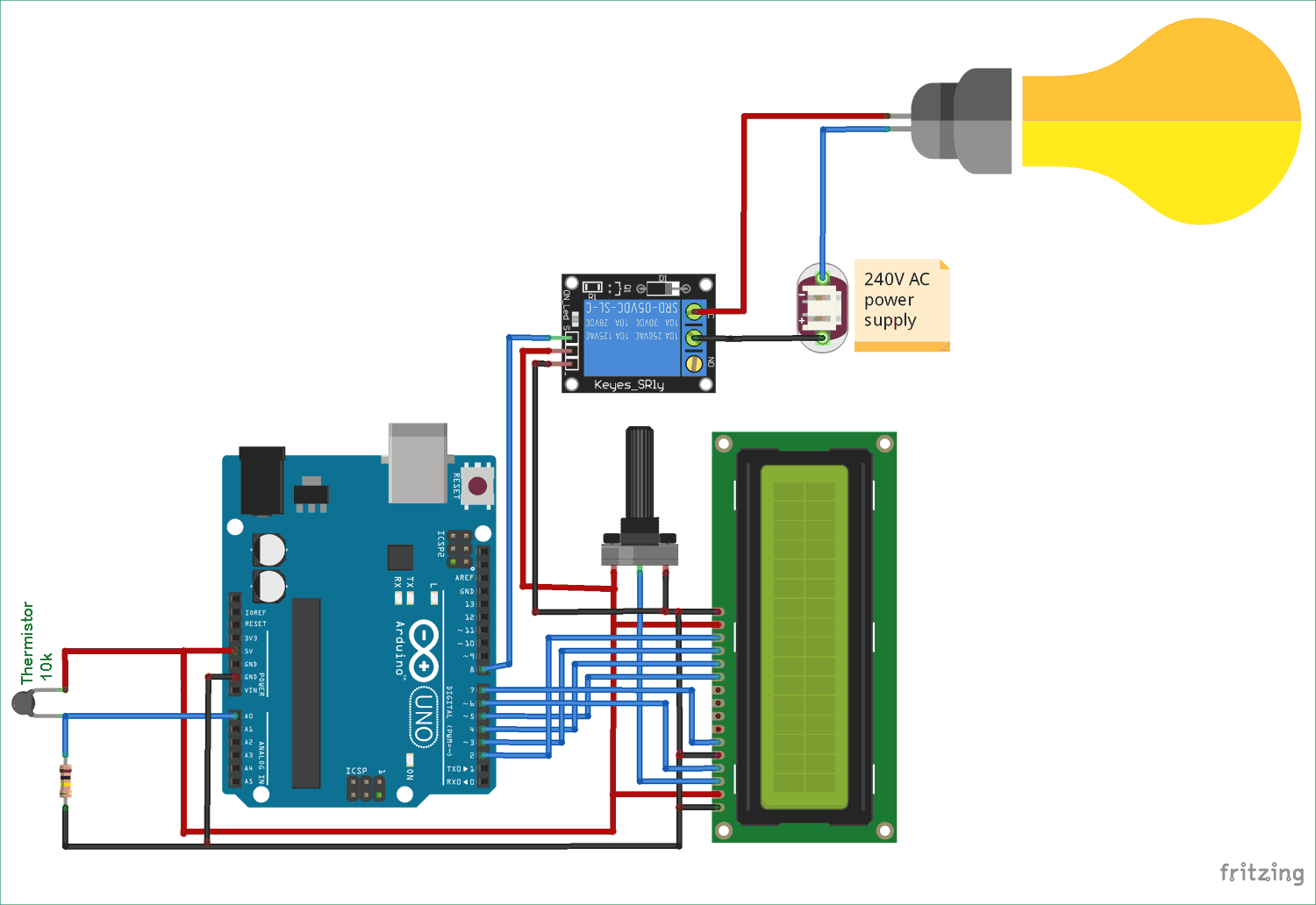
Temperature Controlled AC Home Appliances using Arduino ... from circuitdigest.com The circuit comprises a time base oscillator, a binary counter 8 and a control trigger. Op amplifier temperature switch fan control schematic circuit diagram. If you can read a circuit diagram, you will feel at ease with easy. Published:2014/3/31 21:32:00 author:lynne | keyword: Relays come in several form factors. It consists of a set of input terminals for a single or multiple control signals, and a set of operating contact terminals. Relay schematics and diagrams.is used to control a single circuit, whereas a 5 pin relay switches power between two circuits. Light control relay circuit diagram.
We can control high voltage electronic devices using relays.
The switch s1 and s2 control the relay 1 and relay 2 respectively. A relay is actually a switch which is electrically operated by an electromagnet. Monolithic circuit shown in fig time transmitter circuit xr2242, timing time from a few milliseconds to a few days. Relays control one electrical circuit by opening and closing contacts in another circuit. In the circuit diagram shown, the switch s1 is on and switch s2 is off. This relay circuit is controlled by almost any type of infrared remote controller. Relay schematics and diagrams.is used to control a single circuit, whereas a 5 pin relay switches power between two circuits. Relays are basically switches, switches that you control (turn on or off) by applying or removing a specific voltage to the relay device. If the coil current is suddenly interrupted, a sudden high voltage pulse is developed in the coil. 2.countermeasures for surge voltage of relay control transistor. This circuit is intended to signal when a plant is needing water. The circuit comprises a time base oscillator, a binary counter 8 and a control trigger. A relay driver circuit is a circuit which can drive, or operate, a relay so that it can function appropriately in a in this project, we will build a relay driver for both dc and ac relays.
In the circuit diagram shown, the switch s1 is on and switch s2 is off. A relay is actually a switch which is electrically operated by an electromagnet. Relays come in several form factors. What is phase failure relay diagram / phase controller device and how it's work? A relay is an electromagnetic switch that is used to turn on and turn off a circuit by a low power signal, or where several circuits must be controlled by one signal.
How to use relay with schematic of relay circuit diagram from circuit-diagramz.com The input circuit is the portion of a relays frame to which the. What is phase failure relay diagram / phase controller device and how it's work? If you can read a circuit diagram, you will feel at ease with easy. In this solid state relay circuit triac and moc3021 optocoupler is used. Relays come in several form factors. Ladder diagrams are read from left to right and top to bottom. In the circuit diagram shown, the switch s1 is on and switch s2 is off. Solid state relay is a type of switch to activate load by using without any mechanical parts.
Electronics tutorial about the relay switch circuit and relay switching circuits used to control a variety of loads in circuit switching applications.
If the coil current is suddenly interrupted, a sudden high voltage pulse is developed in the coil. The limitation to the first circuit is that the load current flows through the control pushbuttons. With this control circuit, motion cannot commence (or restart) without the operator's specific pushbutton command. The power source may be either ac or dc, and may. To turn on the motor, the program writes a high value to pin 3, which activates the optocoupler which in turn switches on the transistor. An iron core is surrounded by a control coil. Solid state relay is a type of switch to activate load by using without any mechanical parts. In this solid state relay circuit triac and moc3021 optocoupler is used. First let's take a look at the circuit diagram. Solid state relay is a series that functions like a relay hibryd mechanics. If you can read a circuit diagram, you will feel at ease with easy. Control logic memory or sealed in circuits & energized fluid power dcv. Understanding relays & wiring diagrams what is a relay and how does it work?
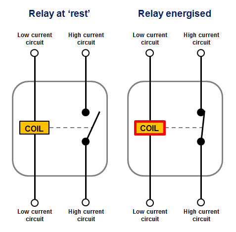
view rain detector circuit diagram. The diagram shows an inner section diagram of a relay. Perhaps the most confusing aspect of relay control circuits for students to grasp is the meaning of normal as it applies to the. Op amplifier temperature switch fan control schematic circuit diagram. Monolithic circuit shown in fig time transmitter circuit xr2242, timing time from a few milliseconds to a few days.
Automotive Relay Guide | 12 Volt Planet from www.12voltplanet.co.uk A relay is actually a switch which is electrically operated by an electromagnet. In this solid state relay circuit triac and moc3021 optocoupler is used. As previously described we will use a 5v adapter as a separate power supply for the electromagnet connected to. Since dc and ac voltages the capacitor absorbs excessive charge and the resistor helps to control the discharge. Solid state relay is a type of switch to activate load by using without any mechanical parts. Electronics tutorial about the relay switch circuit and relay switching circuits used to control a variety of loads in circuit switching applications. With this control circuit, motion cannot commence (or restart) without the operator's specific pushbutton command. Triac is a semiconductor device of silicon controlled rectifier (scr) and works as the transistor but both are different in construction.
As relay diagrams show, when a relay contact is normally open solid state relays consist of an input circuit, a control circuit and an output circuit.
20 amp solar charge controller features, operation schematic circuit diagram. A relay is actually a switch which is electrically operated by an electromagnet. Solid state relay is a type of switch to activate load by using without any mechanical parts. In this diagram circuit using two transistors connected as a high gain compound pair. An iron core is surrounded by a control coil. To turn on the motor, the program writes a high value to pin 3, which activates the optocoupler which in turn switches on the transistor. As relay diagrams show, when a relay contact is normally open solid state relays consist of an input circuit, a control circuit and an output circuit. This circuit works on assumption that almost all remote controller use high frequency circuit diagram is water activated relay circuit. Op amplifier temperature switch fan control schematic circuit diagram. In the circuit diagram shown, the switch s1 is on and switch s2 is off. Perhaps the most confusing aspect of relay control circuits for students to grasp is the meaning of normal as it applies to the. Control logic memory or sealed in circuits & energized fluid power dcv. Relays are basically switches, switches that you control (turn on or off) by applying or removing a specific voltage to the relay device.
Printable Calendar - Printable Calendar Grid - Download a free, printable calendar for 2021 to keep you organized in style. . About printable calendar | www.123calendars.com. Add holidays and events and print the 2021 calendar. Printable calendar 2021 portrait 2021 printable monthly calendar portrait, printable calendar 2021 portrait, if you need help improving your life, you need to prevent squandering time at all expenses. Bring your ideas to life with more customizable templates. Even add notes and about print a calendar. Print these free calendars and enter your holidays and events. Portrait) on one page in easy to print pdf format. Select a category from the printable calendar. Choose from over a hundred calendars. It can be printed as needed, as many copies as needed. 2021 Calendar Printable With Holidays - Printable Calendar from mycalendarlabs.com ...
Усман Масвидаль 2 - Полный бой: Нейт Диаз - Хорхе Масвидаль (UFC 244) - В ночь на 25 апреля (мск) в джексонвилле (сша) прошел турнир ufc 261. . На этот раз усман нокаутировал соперника во. Турнир ufc 261, бой за титул в полусреднем весе: Всего у него 19 побед при одном поражении. Usman vs masvidal 2 on april 24, 2021. В этот раз камару усман больше дрался в. Однако во втором раунде чемпион. На данный момент в его послужном списке значится лишь одно поражение. В начале второго раунда усман выбросил тяжелый правый прямой, которым попал точно в челюсть хорхе. Tristen critchfield whether it's on a full camp or short notice, kamaru usman has the antidote for jorge masvidal. Всего у него 19 побед при одном поражении. Камару Усман о титуле BMF: "Мне не интересен пояс ... from i1.wp.com В ключевом эпизоде поединка усман нанес оппоненту сокрушительный...


Komentar
Posting Komentar